Basement – The LEGO Table

The LEGO Table space in the basement was, for the longest time, the catch all space for anything extra. It was always sort of the last space to get finished up in the basement, though it’s always going to be an ongoing project. A lot of the clean up in this space involved cleaning up other areas first. The initial set up involved a counter sort of unit that I had made years ago, that previously was in my wife’s craft room at the old house. She didn’t need it in the new house, so I inherited it and it was a place to land my LEGO Modulars.

Under was used for storage for most of my other LEGO sets, since I didn’t really have a place to put them yet. They’ve still been in boxes for a few years,

At some point we ended up with some pretty hefty book cases second hand that we were using upstairs for a while, but they were no longer needed. Originally these book cases were going to be used in the basement but they were maybe 4″ too tall, so they ended up in the upstairs space. Since they were available again, I opted to go ahead and trim them down a bit so they would fit in the basement.

This process amounted to marking a line around the top end of the book case, using a circular saw to chop all the way around on the line, then removing the top board from the chopped off scrap bit, and reattaching it to the top of the book case. I also put a fresh new coat of paint on the book cases and shelves, as well as cut a few additional shelves.

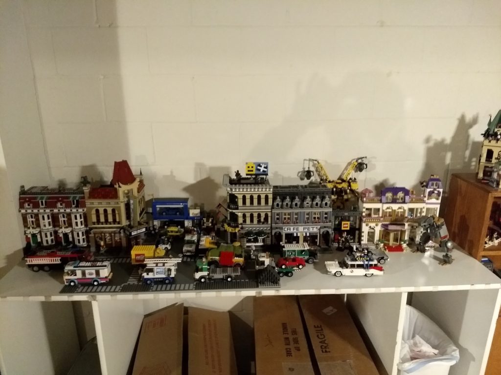
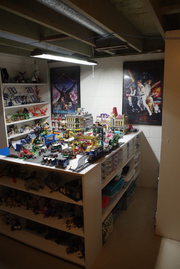
I originally wasn’t sure where these shelves would end up in the basement, but after some measuring, I decided they would work on either side of the LEGO table. This meant turning the LEGO table itself 90 degrees so it sticks out in the room. I also bought some more pre finished shelving boards, like the original table was constructed from, and build what amounted to, a second table, then strapped them together with some braces to double the available surface area.

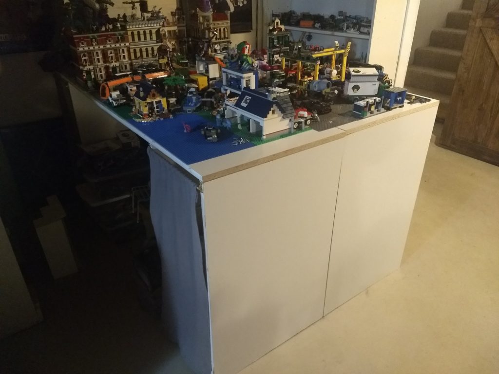
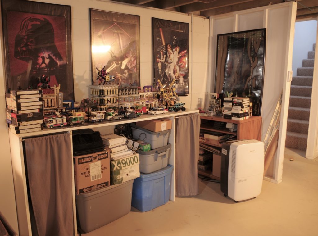
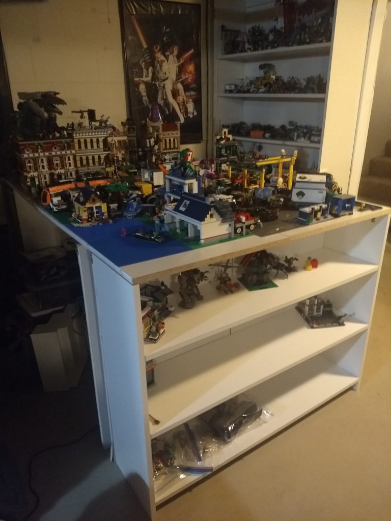
This gave me a lot more room to work with for the LEGO city, as well as shelving on either side to display and store additional sets. Which really cleaned out some of the boxes I had stored under the table. The next part of my plan was to add some additional shelving under the table for storage, which lead me to another idea. Why just add shelving on the sides, when it would be fairly easy to add shelving to the end, for a bit more display space. It also gets rid of this ugly as hell blank white surface.

For this process, I separated the two end legs, and shuffled them back the depth of a narrower (8″ I believe) shelf. Then reattached them. I then cut and assembles a smaller shelf unit and attached it to the end of the LEGO table. On the one side, I also adjusted the secondary leg back, as well as the curtain that was there, so I could keep the trash can under the table and out of view as it was. On the opposite side, I simply removed the extra leg.

Finally, for now, I cut some more 24″ pre finished shelf boards and attached them using L braces, inside the length of the table, on both sides, so the mess inside could become a much more organized, and useful mess. I also picked up an LED shop light that I hung over the length of the table, because this particular corner of the basement is a little dark. It lights up the entire space much better than I had expected it to.

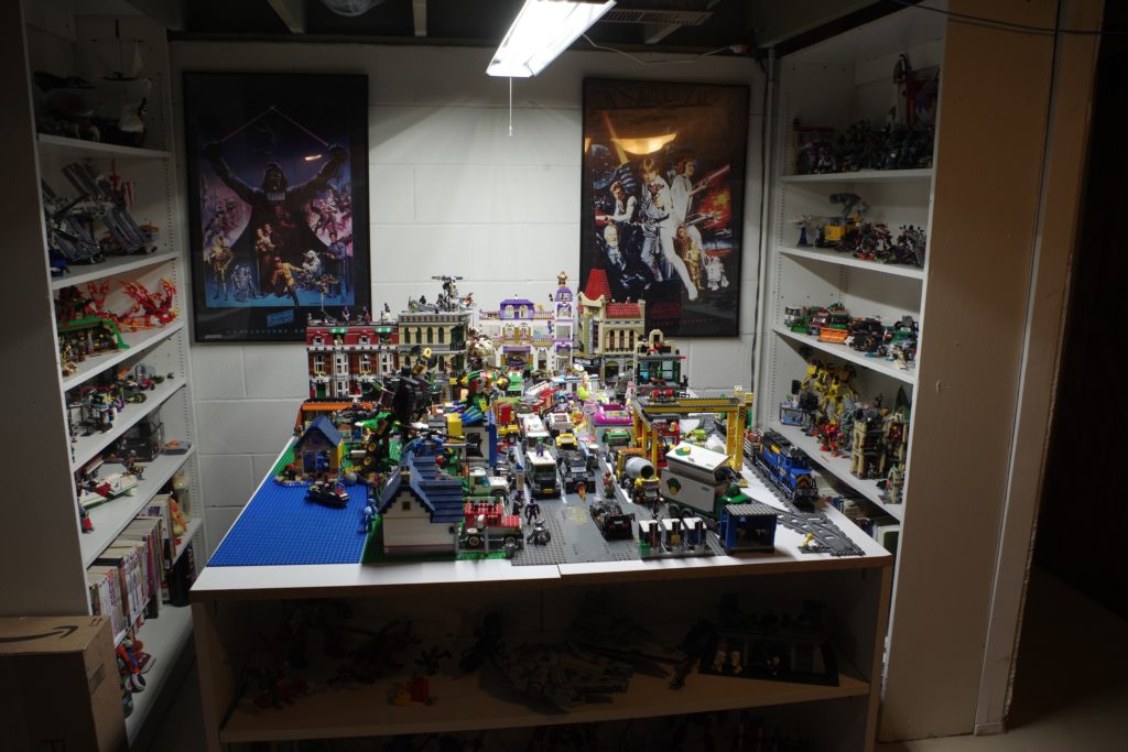
In case you noticed, the Return of the Jedi poster fell off the wall at one point. I want to buy better frames and some fresh posters anyway (these three are like 25 years old now), so I simply hadn’t replaced it on the wall yet.

The next phase of this project is to actually start sorting down the extra LEGO into bins and drawers that will go under the table. I already started this a bit with some IKEA bins but I am going to need more bins than I have and it’s slow going since right now all of the LEGO is just in a giant plastic bin.

Basement – Sliding Door Project

So, I’ve been doing a fair number of projects, but writing about them isn’t one of those projects. Some of it has been improving the basement a bit. Part of the slowness of the basement work is because it occasionally floods a bit. Not really “standing in water” flooding, but “there is a puddle that keeps coming” flooding.

It’s annoying, but I’ve been working to fix it. The house originally didn’t have any downspouts on the gutters, I added those. I’ve added extensions to the gutters to direct water away. I added a new downspout near the area where the water seems to come from to help direct it away more. I cut out some drywall in the underside storage area and pulled the bottom step off of the stairs to fill in some ugly crack-ish spots in the area where the water comes from. At this point, I am waiting for more heavy rain to see if some of this has made any real difference. So far the cement fill seems to have done the best. It’s tricky to describe but basically, the water still came in, but it came in waaaay less and in a slightly different place. So I’m getting there.

I’m not really here to discuss the flooding though. It has affected some decisions on how to make the basement nicer, like I am not going to add Drywall walls like I wanted to. And no carpet, though that was out anyway, because the cats are assholes (We also replaced all of the upstairs carpet with vinyl plank flooring).

One fairly simple project was adding a door. In this case, I put in a sliding barn door style door. My wife wanted to put in a real door but I wasn’t keen on that since there isn’t really a good place for it to open to. The door itself had a couple of motivations behind it.

One, the basement is divided into two halves. One half is semi finished and “nicer” and it’s where I keep my computer and collection of stuff and there is a TV and couch with game consoles and my son has a corner that is his bedroom area when he is around. The other half is under the “original house”, it’s rough, the ceilings are a little low, and there is more duct work and such hanging from the ceiling. We use it for storing all sorts of stuff. It’s really great for that.

The “underside” half is ugly though. I wanted the door to be able to block it out, mostly for aesthetic reasons.

The other purpose of the door is to be able to lock the cats in the basement when we have guests over. My parents and my wife’s parents are all allergic to the cats. We lock some of them in bedrooms, we also lock some of them in the small sunroom/office area upstairs. Sometimes we would lock them in the basement by blocking the stairs with a giant cork board we have that doesn’t really have a home.

Now, we can use the door. It slides between the two openings, stairs and underside storage to block off either one.

One concern was air flow from the storage area, so the door can also be positioned in the middle, which is where it usually sits, so air can flow in and out both sides. It also lifts off easily if I needed to remove it.

The door itself isn’t anything complicated. I could have built a door but I opted to just buy one, though the door was pretty pricey since it needed to be extra wide. The roller kit is a low profile barn door kit, easy enough to install and it nestles up into the floor joist ceiling. The tricky part was that the floor joist didn’t reach the edge of the opening, so I had to screw a couple of 2×4 stand offs to the floor joist to get the door to sit int he proper place. This also meant adding some 2×4 lifts under the stand off to support the immense weight of the door.

I also ended up with an issue of the door rolling slightly. I am not sure if it’s the house or if the rail is a little off (probably a little of both) but the door slides towards the stairs on it’s own. Not very quickly, but it does move.

I solved this with magnets, at the suggestion of my uncle. I didn’t really want an ugly latch that would also potentially end up in the way of the door sliding or people walking. I bought some block magnets and some double sided Gorilla tape (I originally used Command Strips but they were too weak). I stuck a larger magnet to the wall, then two smaller magnets on one end and the center of the door. This allows the door to hold it’s position when blocking the stairs or when positioned halfway.

This project isn’t quite done. I may also add an L bracket of some kind in the center of the door, to hold the door from being leaned outwards, and I want to add a roller on the backside to the whole action is smoother. the way things are, if the cats get determined, they can push the door enough to get it to release from the magnet and escape from the basement.

I also need to adjust that network cable because it’s kind of just there and ugly.

My DIY Dance Dance Revolution Hardpad

IMGP0429Something like ten years or so ago, I built my own hardpad for use on Dance Dance Revolution and Stepmania.  Most of the pads that are easily bought are “soft pads”.  These vary in quality, I have a couple of pads that are pretty light weight and plastic I used ages ago.  These pads tend to get damaged pretty easily, especially when wearing shoes, and slide all over the place when playing.  When i used mine in college I actually taped it to the underside of the rug in the dorm and taped out the grid of squares on the surface, so I could play using my shoes.  I’m sure the people living below me loooove that.  Probably as much as I loved the people above me who played dice constantly.   Some more pricey are made of a thicker though still pliable rubbery material.  These mats slide around less due to the grippy nature of the material, but they can get worn out and damaged by the rough beating of shoes.

The ideal pad is a hard pad.  These can run hundreds of dollars on-line.  They also tend to be large and bulky and heavy.  Shortly after i had finished in college I decided to employ me newly acquired Engineering design skills to build my own Hard Pad.  The electronics part was easy.  I went to the local used game store and asked for the cheapest used PS2 controller they had in stock.  The guy behind the counter actually asked if I was planning to build a DDR pad with it, which was funny since I was.

The pad itself was a bit trickier.  I’d studied several design ideas on-line that others has built.  I wanted something that was less bulky than most of the pads I’d seen.  I also wanted to keep costs down somewhat, which meant using a little material as I could and not having to invest in a bunch of expensive triggers to wire into everything.  The trigger is the key component of course, since it registers the steps when playing.  The dead squares are all just plywood covered in sheet metal.

The sheet metal is also what I ended up using to build the triggers for the step squares.  When you press a key on a video game controller, all that happens is that an electrically conductive pad is flattened and shorts the connection between two copper pads on a PCB board.  When the electrical short is made,  current can flow which causes some chip somewhere to register the button press.  For my step pads, I simply enlarged this process by attaching plates of sheet metal tot he base and to the bottom of each step pad.  To give the pads some cushion and bounce, I placed strips of weather stripping bought at the hardware store between the base and the pad.  Stepping on the pad creates more than enough weight to overpower the weather stripping causing the two sheet metal pads to connect and trigger, stepping off allows the weather stripping to flex back up pushing the pad back to a neutral, unconnected position. I took some CAT 5 cable and soldered it to the sheet metal contacts and the appropriate parts inside the PS2 controller to replicate the button press action inside the controller.

Everything else was cutting wood, attaching corner brackets and attaching sheet metal.   Here are some old photos of the process.

The general construction was sound, but it had a few issues that I never really got around to fixing until more recently.

In the original design, I soldered the connections for the step pads tot he controller’s D-pad.  Mostly because the solder points were larger and easier to solder to.  This had some unintended side effects that made the game unplayable at any higher difficulty level.  By design, the controller never expects opposite D-Pad buttons to be depressed at the same time.  That is, it doesn’t expect the player to press left and right at once, the D-Pad generally controls movement in most games, why would you need to press opposite ways at once.  Dance Dance Revolution has “jumps” in more difficult stages, these are sequences where two arrows have to be matched at the same time, as in “jumped on”.  Since the D-pad doesn’t register left+right or up+down, these jumps would never register and were always considered a miss.  Kind of game play breaking in the case of DDR.

I also wanted to add a box to the set up, to replicate the buttons on the front of a real DDR machine used to select songs and options.  Not something important, but it would add to the effect, and if I ever got really ambitious, I could build a whole cabinet someday.

The other major issue, when I built the original design, I didn’t really do any real management of the wires between the controller and the pad.  They kind of strung around on the sides, they were all too long, and the controller itself was permanently attached to the pad, making moving and storing tricky.  I wanted to make the controller bits, detachable.

I’ve since solved all of these problems with some improvements, all somewhat related.  First problem was the triggers not working for jumps.  This was simple but tedious.  I needed to reqire the buttons from the D-Pad to the face buttons (Triangle, Circle, Square, X).  These work just fine when pressed together, lots of games have combinations where you have to press several buttons at once.

Please Parton my Shoddy Soldering

During this process, I also pitched the controller shaped housing and stuffed everything in a generic electrical project box.  I soldered the 4 shoulder buttons to 4 buttons attached to the box lid, to be used to interfacing with the menus.  Problem 2 solved, everything is in a nice box.

IMGP0430

The last bit was to make the controller easily detachable.  There are 4 pads, each with 2 wires, for a total of 8 wires going from the controller to the pad itself.  I was already using CAT-5 cable for the wire, it had 8 wires in it, so I attached an CAT5 end on the controller piece and a CAT5 receptacle to the dance pad.  Now the two were easily separable and securely attachable.

The ultimate test of course, does it all work?

stepmaniaresults

I’ve run several sets of tracks using the new set up and it certainly does work.  My DDR skill needs a lot of improvement to get back up where it was at my peak, but the pad itself works just fine.  Which is sort of the point, because it really is a fun way to get a pretty good workout in a short period of time.


Raspberry Pi Rack

Even before buying any Raspberry Pi computers, I had this sort of vision for neat rack to put several of them in. The idea evolved a bit as the logistics of it got ironed out but after picking up a second Pi (and planning to get a third), I went and built the thing.

Raspberry Pi Rack

Sorry for the mediocre pictures, I didn’t think to take photos until things were running and I didn’t really want to unplug it. It currently holds a Raspberry Pi B+ and a Raspberry Pi2 B, the B+ is running a ZNC server to keep me connected to several IRC channels and the Raspberry Pi 2B is running a small OpenSIM server, though I’ll probably re-purpose it since in testing performance seems to top out at around 2000 Prim cubes and 4 Avatars. The instance I’ve got running on my VPS is much more suitable. On the other hand, it could be a good place to “archive” builds.

Raspberry Pi Rack

The build itself is pretty straight forward. I used (roughly) the following materials picked up at Lowes:

  • 3 pieces of 10×8 plexiglass cut to 5×7 size.
  • 6 6″ #8 thread rods.
  • 8 (2 packages) of #8 rounded caps.
  • 3 packages of #8 nuts
  • 6″ Micro USB cables from Amazon
  • Cat 5 Cable cut and crimped as needed
  • 1 Netgear Switch I had already
  • 1 Choetech 40W Smart power from Amazon.
  • The smaller screws holding the Pis in are 4mm i believe, and it took two packages of them (16 screws and 32 nuts).

The hardest part was working with the Plexiglass pieces. I could have cut it with the Dremel but the edge would have been all crooked for sure. Instead I scored and snapped them, which did leave a jagged edge on one edge but it could easily be sanded off. On a starting note, the Plexiglass comes with a plastic protective layer, this should be left ON until final assembly to protect the clear surface as much as possible.

Anyway, to cut the sheets down, I used a square and a box cutter to but a line where I wanted the break to be on one side, then clamped the sheet down on the edge of the workbench between the surface and a 2×4. The 2×4 was mostly to help protect the surface of the plexiglass from the clamps. The cut edge should be on the up side, right at the edge of the surface and the 2×4 (or whatever) at the edge on top. The Plexiglass should snap more or less cleanly off. I had some small chips left hanging on the shorter 1″ breaks to shorten the shelves to 7″ from 8″. I used a small hammer while the pieces was still clamped down to chip these down a bit.

The real trick was drilling the holes. In the end, I found the best results came from clamping all of the plastic sheets together between some boards and drilling them all at once. There should be a piece of wood completely covering the bottom of the drilling spot to help support the plexiglass as the drill penetrates through.

I had some trial and error trying to drill my sheets separately, so the holes are not perfect. For the mounting holes I laid the Pi itself where I wanted it and uses a pen to mark the holes. I probably could have done a bit better with a paper guide though.

Assembly was pretty easy, just a lot of tedious screwing of nuts as the thread rods were fed through the holes. Each shelf takes at a minimum, one nut above and below to hold them in place and the rounded caps go on the top and bottom. The power supply and switch are not mounted, they are simply sandwiched in place between the shelves, though the supporting long bars were positioned around the Switch to prevent it from sliding left or right or backwards.

The Power supply I picked because it has two standard wall outlets on one side. I used the Dremel to cut holes in the top sheet to allow these plugs to be accessible. I wanted the unit to be as self contained as possible, these plugs give me a place to plug the Switch in. It’s important when choosing a power supply that it has enough power on all ports to power a Pi. A USB HUB doesn’t work since it will distribute power across all the ports. Several ports I looked at had 2 “high output” ports for iPads and iPhones but the rest were lower output.

The USB power cables were 6″ jumpers I found on Amazon and the CAT 5 cable were small jumpers I made myself with ends and a crimper. When I add the back two Pis I’ll need different cables though, likely cables with a 90 degree connector and definitely longer ones.

Raspberry Pi Rack

The whole package sits nicely on top of my desktop box next to my Synology NAS.