Projects

OSEPP Arduino Starter Kit

Arduino and a Raspberry Pi 2BSo, a month or so ago, while traveling for work, I was bored in the hotel room and found out there was a Fry’s Electronics around the corner from the hotel. I decided to pop in and look around and see if I could find anything interesting. I also wanted to see how much Raspberry Pi 2B boards were there (and if they were comparable to Amazon.) They had a couple of Pis, a large selection of basic electronic components and a pretty decent selection of Arduino shields and parts.

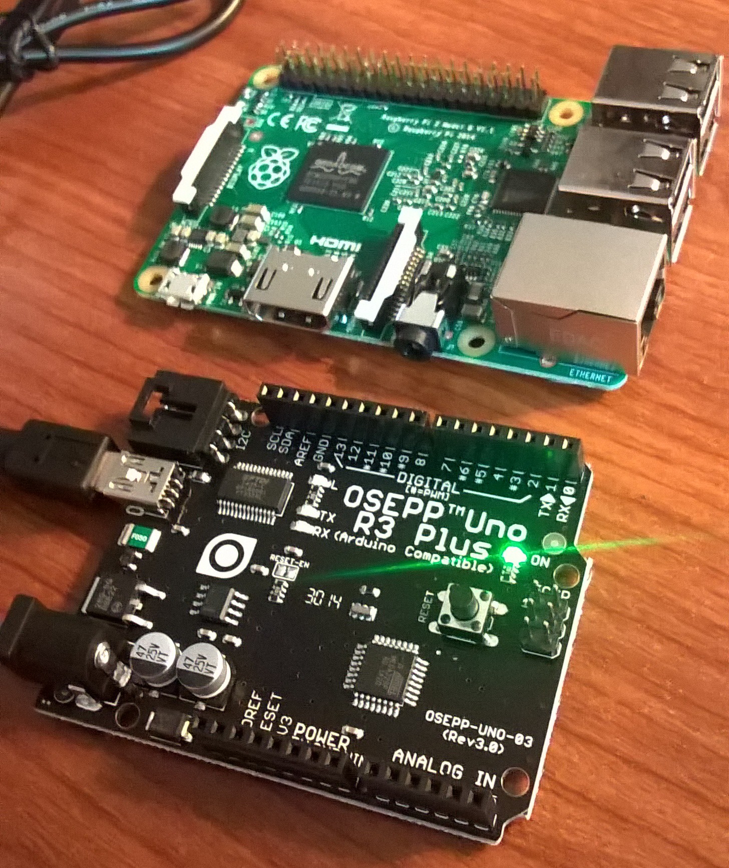
I’d been looking into getting an Arduino for a while and decided what the hell. There may have been single packed Arduino boards but I really couldn’t tell from the cards which was the base board an which was just an add on shield. I ended up with the OSEPP Arduino Basic Starter Kit.  Honestly, since I hadn’t ever used an Arduino, I didn’t own an Arduino, and I had some basic but not super amazing electronics skills, this really was the best choice.

The kid includes a lot of nice basic parts as well as a guide book to get you started using these basic parts.  The box itself promotes the major projects of “Volt Meter”, “LED Game” and “Electronic Buzzer”.  It also runs through the basics of lighting up some LEDs.  The tutorials are decent though I wish there was a little more on the basics of how to work the bread board and the little wires.  It’s not hard to figure out, but it also isn’t super self explanatory if you didn’t have any experience with electronics at all.  the Volt meter tutorial is less exciting than hoped and the Buzzer just runs up the music scales but it could be modified to play a tune using the little piezo buzzer.

WP_20150630_09_21_48_Pro
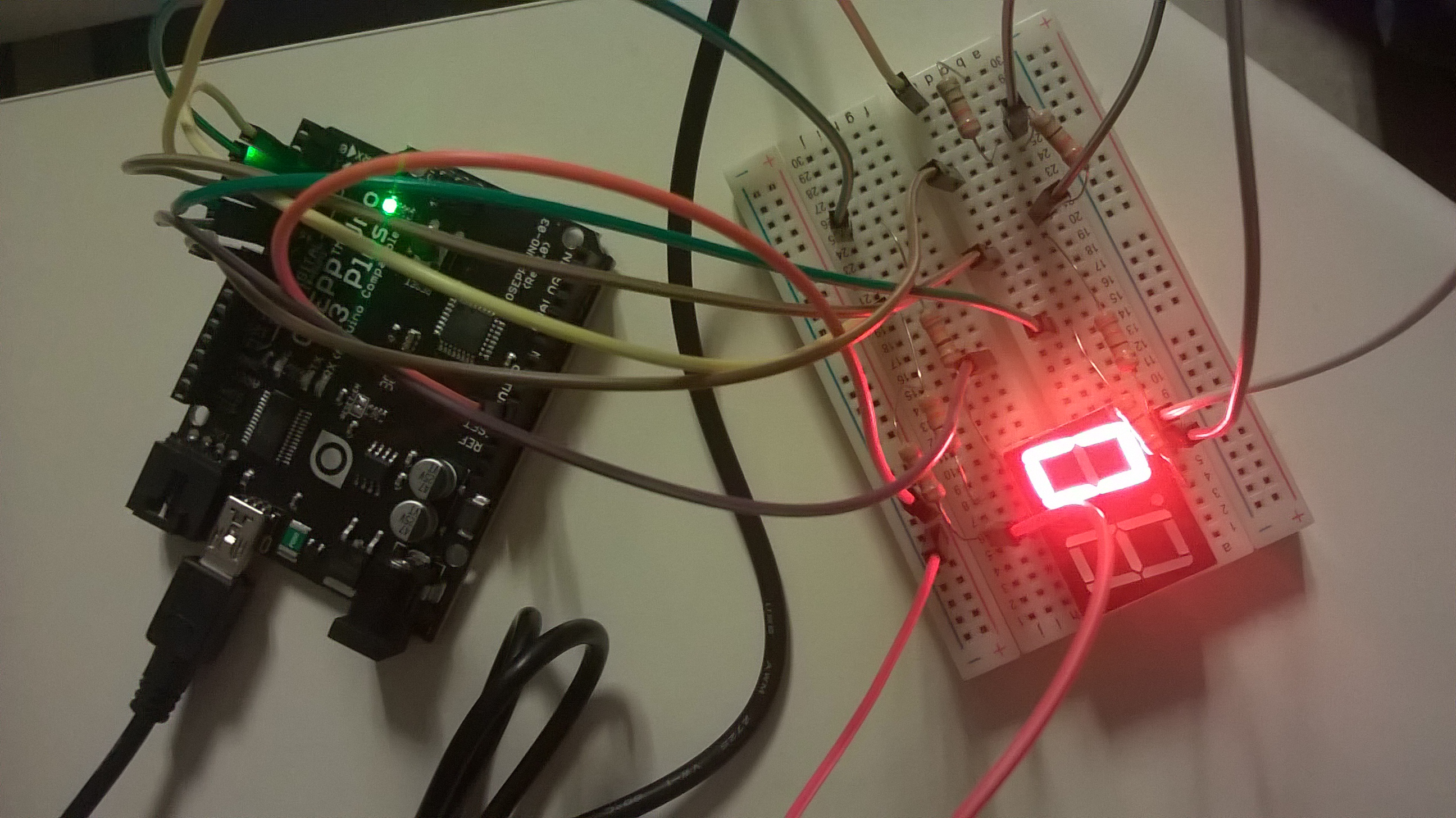
The LED game is neat, but simple.  You make the lights flash in sequence and you must press the button when the appropriate light is flashing, which causes the lights to flash faster.  There is also a 7 segment LED in the kid, which you make count down from 9 to 0.  This actually has a lot of fun potential and I have some ideas for it but I need to figure out how to light up both numbers to display a number (such as say, a temperature).

After exhausting the fun of the starter manual, on my next trip to the area, I bought a temperature and humidity sensor and wired it up.  This was a bit trickier since it required figuring out how to find and download the necessary libraries and modifying the code a bit to get it to read properly.  In the end, I managed to get things working though, which was kind of great since the AC in my hotel room didn’t have a digital read out, so I could know exactly how cold it was and why I was either freezing or sweating.

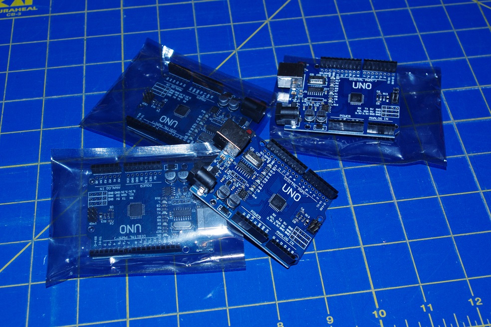
So, fast forward a bit more again, I’ve got some fun ambitions going and the idea of playing with several Arduino projects.  Unfortunately, while cheap, Arduino boards can add up to expensive.  Unless you buy cheap Chinese knockoffs for $3 apiece off of AliExpress.  I also have some cheap Network boards and temperature sensors coming.  Five boards total, five sensors and two network shields, for around $35, really isn’t too bad of a deal if it all works.

And thus, I have a ton of Arduino boards to play with now.

IMGP5277


Raspberry Pi Rack

Even before buying any Raspberry Pi computers, I had this sort of vision for neat rack to put several of them in. The idea evolved a bit as the logistics of it got ironed out but after picking up a second Pi (and planning to get a third), I went and built the thing.

Raspberry Pi Rack

Sorry for the mediocre pictures, I didn’t think to take photos until things were running and I didn’t really want to unplug it. It currently holds a Raspberry Pi B+ and a Raspberry Pi2 B, the B+ is running a ZNC server to keep me connected to several IRC channels and the Raspberry Pi 2B is running a small OpenSIM server, though I’ll probably re-purpose it since in testing performance seems to top out at around 2000 Prim cubes and 4 Avatars. The instance I’ve got running on my VPS is much more suitable. On the other hand, it could be a good place to “archive” builds.

Raspberry Pi Rack

The build itself is pretty straight forward. I used (roughly) the following materials picked up at Lowes:

  • 3 pieces of 10×8 plexiglass cut to 5×7 size.
  • 6 6″ #8 thread rods.
  • 8 (2 packages) of #8 rounded caps.
  • 3 packages of #8 nuts
  • 6″ Micro USB cables from Amazon
  • Cat 5 Cable cut and crimped as needed
  • 1 Netgear Switch I had already
  • 1 Choetech 40W Smart power from Amazon.
  • The smaller screws holding the Pis in are 4mm i believe, and it took two packages of them (16 screws and 32 nuts).

The hardest part was working with the Plexiglass pieces. I could have cut it with the Dremel but the edge would have been all crooked for sure. Instead I scored and snapped them, which did leave a jagged edge on one edge but it could easily be sanded off. On a starting note, the Plexiglass comes with a plastic protective layer, this should be left ON until final assembly to protect the clear surface as much as possible.

Anyway, to cut the sheets down, I used a square and a box cutter to but a line where I wanted the break to be on one side, then clamped the sheet down on the edge of the workbench between the surface and a 2×4. The 2×4 was mostly to help protect the surface of the plexiglass from the clamps. The cut edge should be on the up side, right at the edge of the surface and the 2×4 (or whatever) at the edge on top. The Plexiglass should snap more or less cleanly off. I had some small chips left hanging on the shorter 1″ breaks to shorten the shelves to 7″ from 8″. I used a small hammer while the pieces was still clamped down to chip these down a bit.

The real trick was drilling the holes. In the end, I found the best results came from clamping all of the plastic sheets together between some boards and drilling them all at once. There should be a piece of wood completely covering the bottom of the drilling spot to help support the plexiglass as the drill penetrates through.

I had some trial and error trying to drill my sheets separately, so the holes are not perfect. For the mounting holes I laid the Pi itself where I wanted it and uses a pen to mark the holes. I probably could have done a bit better with a paper guide though.

Assembly was pretty easy, just a lot of tedious screwing of nuts as the thread rods were fed through the holes. Each shelf takes at a minimum, one nut above and below to hold them in place and the rounded caps go on the top and bottom. The power supply and switch are not mounted, they are simply sandwiched in place between the shelves, though the supporting long bars were positioned around the Switch to prevent it from sliding left or right or backwards.

The Power supply I picked because it has two standard wall outlets on one side. I used the Dremel to cut holes in the top sheet to allow these plugs to be accessible. I wanted the unit to be as self contained as possible, these plugs give me a place to plug the Switch in. It’s important when choosing a power supply that it has enough power on all ports to power a Pi. A USB HUB doesn’t work since it will distribute power across all the ports. Several ports I looked at had 2 “high output” ports for iPads and iPhones but the rest were lower output.

The USB power cables were 6″ jumpers I found on Amazon and the CAT 5 cable were small jumpers I made myself with ends and a crimper. When I add the back two Pis I’ll need different cables though, likely cables with a 90 degree connector and definitely longer ones.

Raspberry Pi Rack

The whole package sits nicely on top of my desktop box next to my Synology NAS.

Raspberry Pi Project 01 – Web Server

Raspberry-Pi-Logo So, just as a start, this isn’t a how to of any kind.  There are already plenty of tutorials on how to do whatever with the raspberry Pi.  Unless I’m pushing something unique, I don’t feel the need to provide another explanation of how to do the same thing a hundred other people have done.

I completed my first trial project on my Raspberry Pi of setting up a web server.  This is a pretty simple process that I have done dozens of times before on Ubuntu and Windows so it isn’t exactly an amazing feat.  The most amazing part is that I followed through on it instead of putting the Pi aside for “someday” like so many other projects.

The set up is really straight forward.

sudo apt-get install apache2

sudo apt-get install php

sudo apt-get install mysql

wget wordpress from wherever

sudo apt-get install vsftp

sudo mysql

create database wordpress

Futz with some permissions…

That’s it, pretty much the same as Ubuntu.  I guess this is a hot to after all.  I followed up by setting up WordPress through the WordPress interface.  I added a theme and some plug ins and created a few dummy posts.  Mostly I wanted to gage performance.  Granted, a single user web server sitting inside a firewall on a LAN is probably not the best way to gage functionality.

Everything ran fine though.  FTP uploads were a little slow, but I imagine part of that can be attributed to the memory card access speeds.  It wasn’t unbearably or unusably slow.

The main issue is that, I already run a private web server on a full blown machine inside my house.  It’s useful for playing with web dev stuff, I run a WordPress instance archiving all of my posts online together, I host a couple of other web apps for things like my webcams and Twitter analytics.  It is already running and does more than the Pi is probably capable of doing all at once.

Using my Pi as a single WordPress host is a waste of a good Pi.  It was a nice exercise to get familiar with the mechanics of the Pi, but it’s not really all that useful long term.  So I’ve wiped it out to move on to a new project.

I’ve been debating on what to use it for on my second Project.  I have been flip flopping between an XBMC media player and running Retro Pi to make it into an emulation station.  My main hang ups, the media player won’t be super useful without a media server to back it up.  I plan to buy a NAS later this year and start ripping all of my DVDs to it but that’s months off.  Retro Pi seems like the logical choice then except I have an old Netbook with a busted screen I plan to use to for building a retro arcade machine.  Still, it might be good to compare the Pi to the Netbook for the emulation station.  Also, I have more than one room so I could use two emulation boxes pretty easily.  I thought about using the Netbook guns to build a Stepmania/DDR box anyway, and it’s probably better suited to run Stepmania than the Pi is anyway.

Anyway, as usual, lots of ideas, lots of plans, maybe something fun will come out of it.

Weekend Project – Picket Fence Shelf

Just wanted to show off a little recently completed wood project.  My brother ended up with a huge pile of extra fence pickets and I put some of them to good use making some shelf units for my daughter.

IMGP0990

The process was pretty straight forward, each shelf consists of 11 pickets and 3-4 30″ boards.  The board length is variable of course which may alter the number of pickets needed.

First, I did a rough sand job of each picket, rough because I wanted to remove the worst of the rough bits but leave some of the overall “rustic” roughness of the surface.  The pickets were also trimmed off by 1″ incrementing lengths (1″, 2″, 3″, etc) so they would stair step across the back.  The boards for the shelves were also cut from an 8 foot 1×10″ board.

At this point, everything was painted with several coats of white paint.

Assembly is a bit tricky but by the third shelf I had a pretty good method down.  The side pieces get marked for where the shelves should fall (variable intervals depending on needs).  Then the side shelves are screwed onto the ends of each shelf in the appropriate places (I just screwed right through into the ends of the shelves, careful not to split things).  Two screws each picket, each shelf point.

Then I measured out from the edges on the backside to line up the longest center picket in the middle, this is then screwed down with a 1/4″ off set from the bottom from the sides.  This will leave a small gap along the bottom along the back.  The purpose is to make the unit more stable so it will only hit the floor on the side pickets.  Getting 4 side pieces to sit flat as legs is a lot easier than getting 11 pickets to line up flat on the ground (which would cause the shelf to wobble).

Next the two shortest back pickets are attached along the edges of the back.  The remaining pickets get attached last and I found it was easy enough to just eyeball the spacing.

I also added some simple boxes to the bases of two of the shelves to give some added height (as pictured above).  This part is optional.

Security Phase 2 – Doors and Windows (Planning)

I just wanted to start off by saying, this isn’t a how to at all, it’s more some general ideas I’ve been looking over for how to add door and window security to my recently set up video monitoring system.  Basically, I want a log of when and if the doors and windows are opened and closed.  I’d prefer not to run a bunch of wires, so wireless sensors are in order.

What I ultimately want is for an indicator light on a webpage to change based on the status of the door or window, a timestamp log to be created and possibly for some sort of email or text alert to occur.  ULTIMATELY I may even use this whole project as an excuse to finally develop my Phone app skills and build an app that I can view it all on, but that’s farther down the road.  A basic web page is fine for now, and it’s something I can manage.

My worry with wireless sensors was that I’d have to constantly change the batteries.  Until I realized that it would be trivial to design the sensor so that it only transmits when the window is open, and while I am not building my own sensors (I probably could) I imagine the makers of such sensors realize that you could save a ton of battery life by designing the sensors to only work when open.  I did a bit of searching on Amazon and found a6 pack of sensors for less than ten dollars.  It appears that each sensor has it’s own receiver/indicator which emits an audible tone.

This is actually probably alright for my needs.

While I am not an Electrical Engineer, I am familiar with basic circuit flow and basic electronics.  I don’t have any of these sensors yet but I can make some basic assumptions based on what I know.   When the window/door is opened, some trigger is closed and the sensor starts transmitting some sort of radio signal.  The fob thing which is always listening will receive the signal and activate some sort of internal speaker. 

There are a couple of issues that need to be solved here.  One, while the sensors hopefully are designed to conserve battery power, the FOBs are probably not.  I also want the signal to go to a computer and not sound a mostly useless audible alarm.  The power issue isn’t a huge issue.  With the right transformer brick providing the proper voltage, it wouldn’t be hard to rewire the contacts to allow for the units to be plugged into the wall, all at once, off of one power supply.  They look to be small enough that they could be mounted inside an electrical box in a small array and wired for power.

A similar method can be used to transform the speaker signal into a trigger for some sort of simple IO board.  To activate the speaker, some sort of voltage is applied to the speaker, the speaker can easily be removed and the contact points that would previously have fed the speaker could be wired to am IO board.  When the voltage is supplied to the "speaker" it will instead be read by the IO board, triggering a signal that "the Window/Door is open."

The main puzzle I have right now is, what would work best for the IO board.  I see two options here, and both would function differently, and I may even require both.  I could go with an Arduino board or a Raspberry Pi.  Both of these options seem to have advantages and disadvantages, and there may even be a third option which corrects the disadvantages.

arduino

Let’s look at the Arduino.  The Arduino is ideal for dealing with the IO board.  It is, by design, meant to work with this sort of "hands on" electronics systems.  It even has build in contacts for working with two wire IO interfaces.  I don’t know anything about Process, the programming language of the Arduino, but I’ve been meaning to learn and I am capable of learning it.  The problem is on the output.  Arduino is not designed to work with PCs in any simple way.  From some quick research online, the Arduino would require a serial interface and likely special software running on the server to poll the Arduino at set intervals.  Which brings up another issue.  As near as I can tell, the Arduino is a "pull" interface, meaning the server would have to pull the status from the Arduino, as opposed to "push" where the Arduino would push the data to the server as it changes.

Raspberry_Pi_Photo

So there is also the Raspberry Pi.  The Raspberry Pi is a computer itself, which makes interfacing with the server simple and easy.  It runs a simplified OS but connecting the Pi to the network is simple and telling it to push even a text file status update to the server via FTP or some similar network protocol is trivial.  the issue comes in the need to read the sensors.  I’m not entirely sure the Raspberry Pi is even capable of reading an analogue IO interface right out of the box.  Some searching suggests it is possible through an additional interface board of some sort but not right out of the box.  Looks like there are a handful of GPIO points build into the PI.  The PI also feels like much more than is really needed for this simple application.

Its kind of a tricky decision, I’ve been wanting to play around with both the Pi and the Arduino so I may just pick up one of each and see what works.  Both are around the same price and the whole system in the end will end up costing around $50-$75, which is almost nothing.  The final step once the sensor data lands on the server is updating the web page but I already am familiar enough with building webpages and simple polling scripts that this step is the easy part.  Whatever I end up going with I’ll certainly document the results in the future.