My DIY Dance Dance Revolution Hardpad
 Something like ten years or so ago, I built my own hardpad for use on Dance Dance Revolution and Stepmania. Most of the pads that are easily bought are “soft pads”. These vary in quality, I have a couple of pads that are pretty light weight and plastic I used ages ago. These pads tend to get damaged pretty easily, especially when wearing shoes, and slide all over the place when playing. When i used mine in college I actually taped it to the underside of the rug in the dorm and taped out the grid of squares on the surface, so I could play using my shoes. I’m sure the people living below me loooove that. Probably as much as I loved the people above me who played dice constantly. Some more pricey are made of a thicker though still pliable rubbery material. These mats slide around less due to the grippy nature of the material, but they can get worn out and damaged by the rough beating of shoes.
The ideal pad is a hard pad. These can run hundreds of dollars on-line. They also tend to be large and bulky and heavy. Shortly after i had finished in college I decided to employ me newly acquired Engineering design skills to build my own Hard Pad. The electronics part was easy. I went to the local used game store and asked for the cheapest used PS2 controller they had in stock. The guy behind the counter actually asked if I was planning to build a DDR pad with it, which was funny since I was.
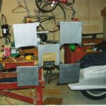
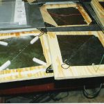
The pad itself was a bit trickier. I’d studied several design ideas on-line that others has built. I wanted something that was less bulky than most of the pads I’d seen. I also wanted to keep costs down somewhat, which meant using a little material as I could and not having to invest in a bunch of expensive triggers to wire into everything. The trigger is the key component of course, since it registers the steps when playing. The dead squares are all just plywood covered in sheet metal.
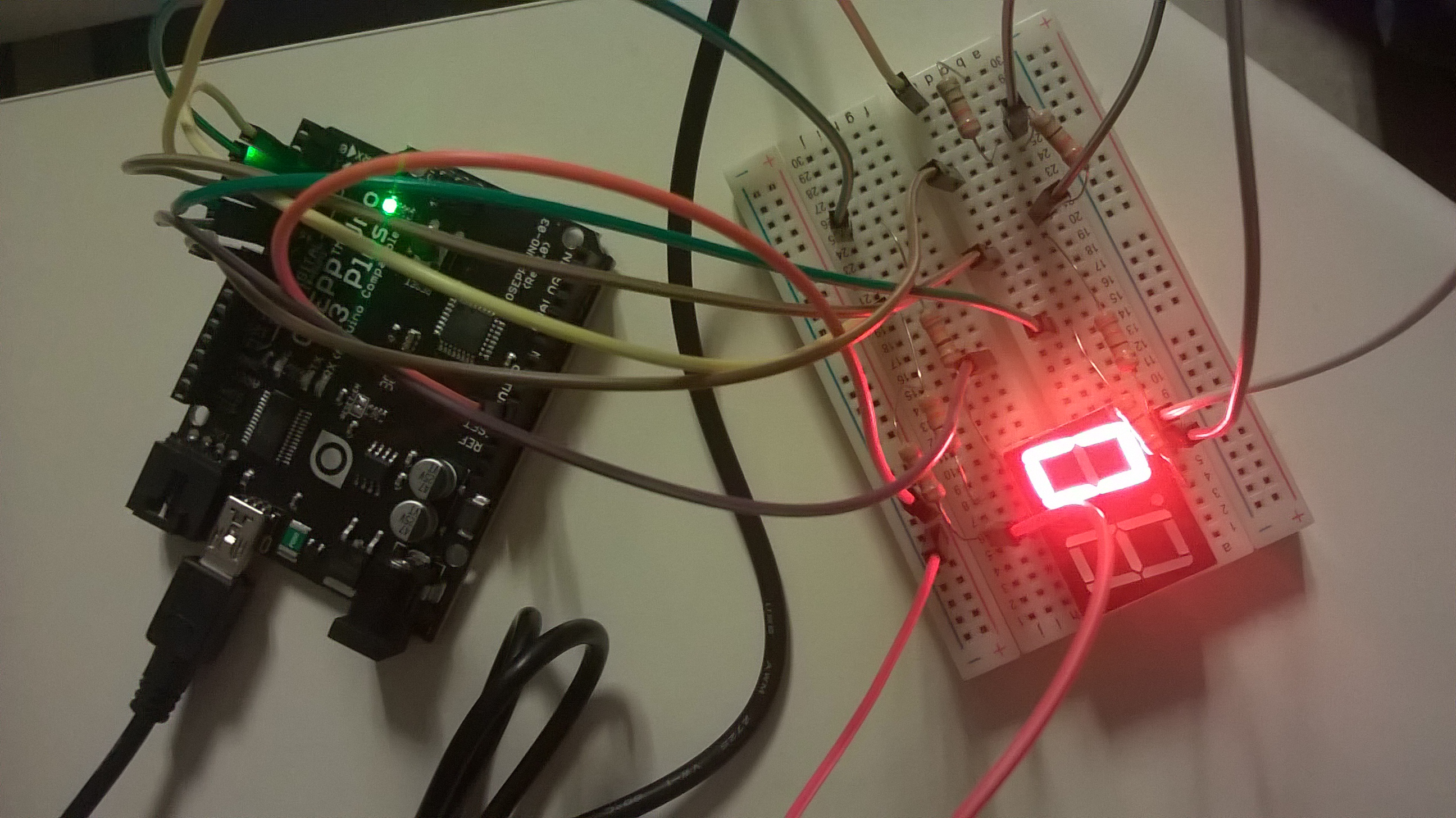
The sheet metal is also what I ended up using to build the triggers for the step squares. When you press a key on a video game controller, all that happens is that an electrically conductive pad is flattened and shorts the connection between two copper pads on a PCB board. When the electrical short is made, current can flow which causes some chip somewhere to register the button press. For my step pads, I simply enlarged this process by attaching plates of sheet metal tot he base and to the bottom of each step pad. To give the pads some cushion and bounce, I placed strips of weather stripping bought at the hardware store between the base and the pad. Stepping on the pad creates more than enough weight to overpower the weather stripping causing the two sheet metal pads to connect and trigger, stepping off allows the weather stripping to flex back up pushing the pad back to a neutral, unconnected position. I took some CAT 5 cable and soldered it to the sheet metal contacts and the appropriate parts inside the PS2 controller to replicate the button press action inside the controller.
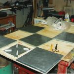
Everything else was cutting wood, attaching corner brackets and attaching sheet metal. Here are some old photos of the process.
The general construction was sound, but it had a few issues that I never really got around to fixing until more recently.
In the original design, I soldered the connections for the step pads tot he controller’s D-pad. Mostly because the solder points were larger and easier to solder to. This had some unintended side effects that made the game unplayable at any higher difficulty level. By design, the controller never expects opposite D-Pad buttons to be depressed at the same time. That is, it doesn’t expect the player to press left and right at once, the D-Pad generally controls movement in most games, why would you need to press opposite ways at once. Dance Dance Revolution has “jumps” in more difficult stages, these are sequences where two arrows have to be matched at the same time, as in “jumped on”. Since the D-pad doesn’t register left+right or up+down, these jumps would never register and were always considered a miss. Kind of game play breaking in the case of DDR.
I also wanted to add a box to the set up, to replicate the buttons on the front of a real DDR machine used to select songs and options. Not something important, but it would add to the effect, and if I ever got really ambitious, I could build a whole cabinet someday.
The other major issue, when I built the original design, I didn’t really do any real management of the wires between the controller and the pad. They kind of strung around on the sides, they were all too long, and the controller itself was permanently attached to the pad, making moving and storing tricky. I wanted to make the controller bits, detachable.
I’ve since solved all of these problems with some improvements, all somewhat related. First problem was the triggers not working for jumps. This was simple but tedious. I needed to reqire the buttons from the D-Pad to the face buttons (Triangle, Circle, Square, X). These work just fine when pressed together, lots of games have combinations where you have to press several buttons at once.
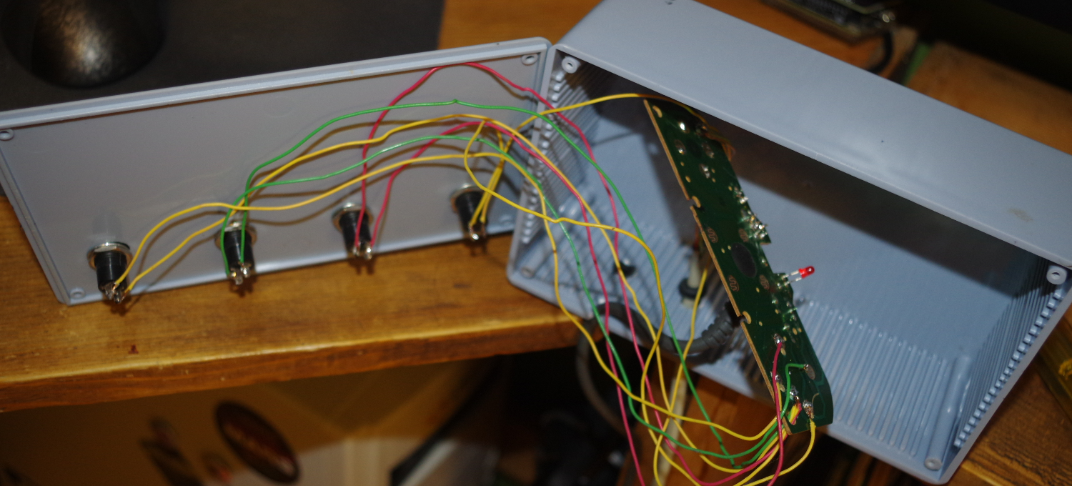
During this process, I also pitched the controller shaped housing and stuffed everything in a generic electrical project box. I soldered the 4 shoulder buttons to 4 buttons attached to the box lid, to be used to interfacing with the menus. Problem 2 solved, everything is in a nice box.
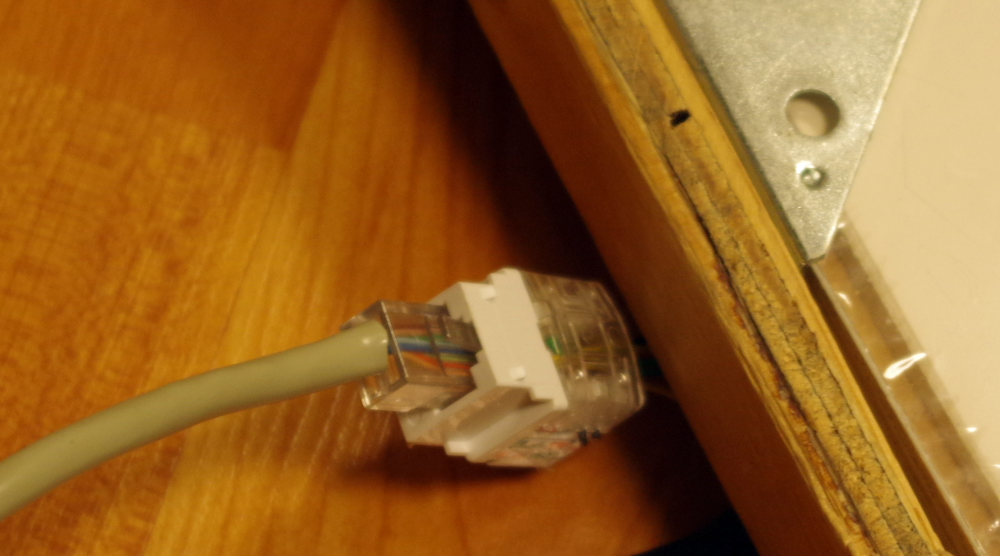
The last bit was to make the controller easily detachable. There are 4 pads, each with 2 wires, for a total of 8 wires going from the controller to the pad itself. I was already using CAT-5 cable for the wire, it had 8 wires in it, so I attached an CAT5 end on the controller piece and a CAT5 receptacle to the dance pad. Now the two were easily separable and securely attachable.
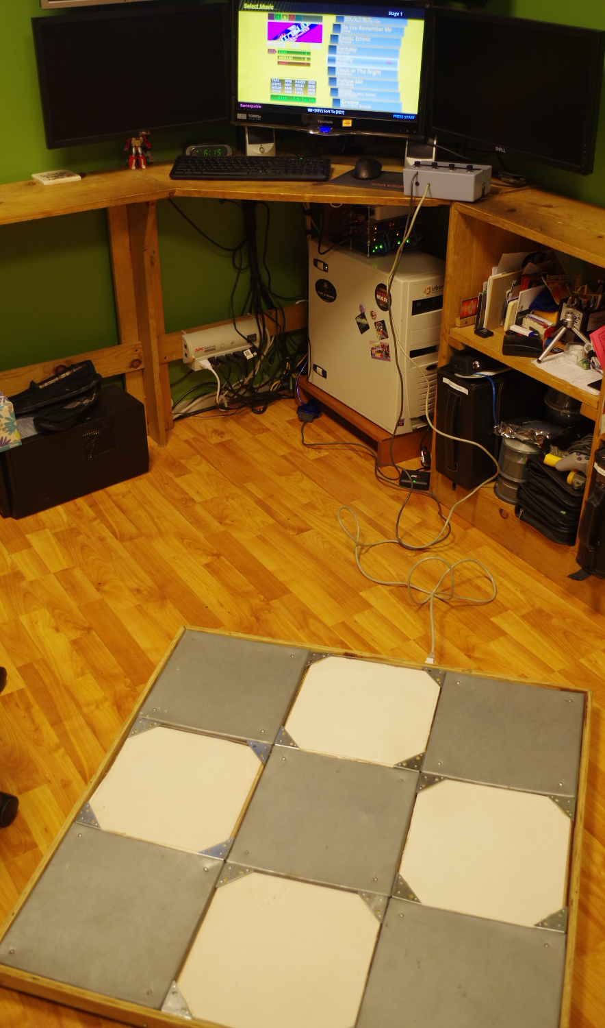
The ultimate test of course, does it all work?
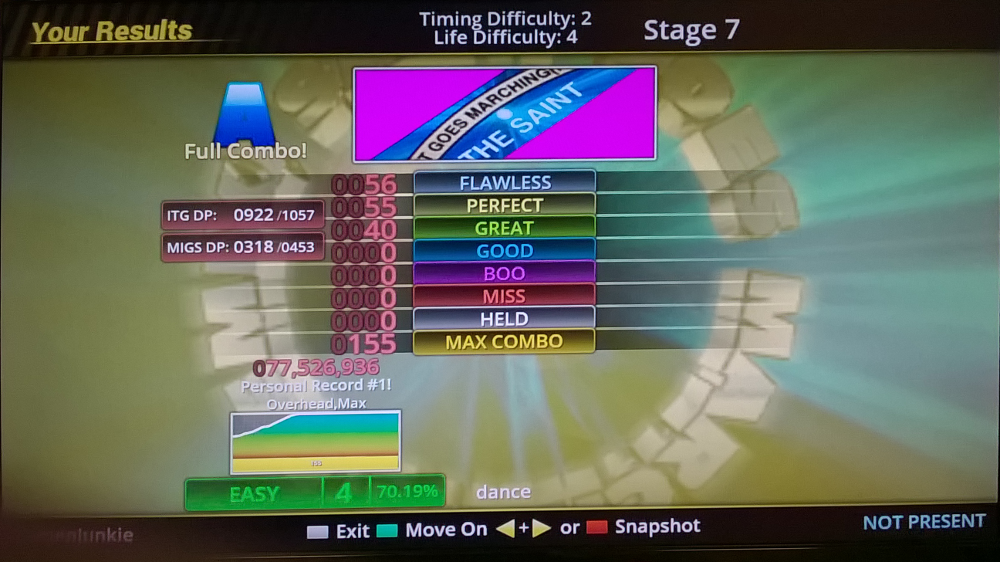
I’ve run several sets of tracks using the new set up and it certainly does work. My DDR skill needs a lot of improvement to get back up where it was at my peak, but the pad itself works just fine. Which is sort of the point, because it really is a fun way to get a pretty good workout in a short period of time.
Josh Miller aka “Ramen Junkie”. I write about my various hobbies here. Mostly coding, photography, and music. Sometimes I just write about life in general. I also post sometimes about toy collecting and video games at Lameazoid.com.