IOT Projects

Keyboard Jiggler with Python and Raspberry Pi

So I did a pretty simple but amusing little project recently, a bit on a whim. Let’s say, I have a few games that it would be useful to just, let idle for experience or whatever. The problem is, that these games also have built-in idle deterrence. Your character falls asleep, or you just time out of the game after five or ten minutes.

I initially start off trying to use AutoHotkey, a program that basically does what I wanted here, you program it to press keys at certain intervals, basically just a simple keep-alive movement every couple of minutes.

It turns out, at least one of these games detects Autohotkey as a cheat, and won’t launch when it’s running.

I got to thinking, I could probably program one of my Arduino boards to emulate a keyboard. And sure enough, there are libraries for this very task. Then I discovered that, the keyboard library does not work on my old Uno boards. But I found an alternative route with my Raspberry Pi Pico that I picked up a few years ago. The Pico could probably do what I needed as well.

After some digging online, I found plenty of guides on how to build a full-sized Keyboard using GPIO pins on the Pico, but nothing quite exactly what I needed, but there was enough Python Code available, I could figure it out pretty easily by stripping apart some full keyboard code. Instead, I just started with a simpler macro button keyboard script. Most of the scripts I came across have code to detect and save a button press, then send the command using the Python Keyboard library. I just stripped all that out and put it on a timer loop with some simple, regular input. A set of repeated w presses, follow d by repeat d presses of a, s, and d.

Essentially, “walk in a little square loop.”

Step one was to set up Circuit Pi on the Pi Pico, which is detailed here, though only the initial setup is needed.

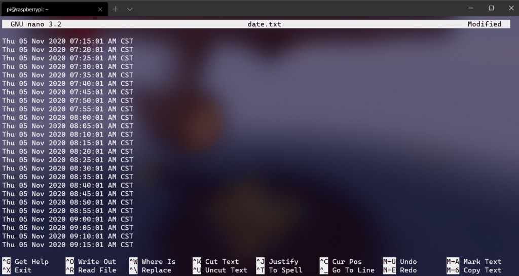
The test using Notepad worked perfectly, aside from one annoying issue, I could not easily edit the code while the device was plugged in, because the test loop would spit out wwwaaasssddd every 5 seconds.

After some careful quick timing, I adjusted that out to every 300 seconds (5 minutes).

It was time to test things out. Before work, I set the game running and the keyboard Jiggler working. When I came back later it was working just fine.

But there were some issues, one of which I could mostly address.

Firstly, the thing just runs, forever. It doesn’t really need to, I only need it going for around 3-4 hours. I added a counter variable to the script that would count how many runs through the loop had occured, and if it was more than a set amount, it would break the loop, which would stop the scripted movement and idle out of the game.

The other two issues are less easy to solve.

One, I had a thought that I could remote to my PC and swap games halfway through the day (at lunch). Except when you leave Remote Desktop, it locks the remote PC. Meaning the game loses focus and the keyboard Jiggler stops working. It’s literally a hardware device that pretends to be a keyboard.

The second issue, that could be easy to solve with some habit changes. I, very often, will use Firefox’s Tab Share to send tabs to either my desktop or my laptop. These are articles I want to clip and save, something I may want to buy later, notes for some projects I had done. Basically, it’s a way to send myself a reminder of something I don’t want to deal with on my phone. When I send a tab, on the remote machine, Firefox pops up and takes focus, meaning, once again, the game idle breaker stops working and it idles out.

The solution here is to just, get into the habit of only sending tabs after noon or so.

Another little improvement I added was a bit of randomization. I am not really worried about “detection,” but it’s easy to avoid by simply, adjusting the 5-minute timer to be random movement between 4 and 5 minutes, as well as randomizing what the movement is a bit.  I also added a bit of correction if the player moves too far away from the starting position.

Anyway, the script below is the completed script.

import time
import random

import board
import digitalio
import usb_hid
## Aquired from https://github.com/adafruit/Adafruit\_CircuitPython\_HID
from adafruit_hid.keyboard import Keyboard
from adafruit_hid.keyboard_layout_us import KeyboardLayoutUS
from adafruit_hid.keycode import Keycode

time.sleep(1)
keyboard = Keyboard(usb_hid.devices)
keyboard_layout = KeyboardLayoutUS(keyboard)  # We're in the US :)
led = digitalio.DigitalInOut(board.LED)
led.direction = digitalio.Direction.OUTPUT
total_runs = 0
running = True
# This is the choices for keys to randomly choose from, this is standard WASD
# This could be changed to be whatever to choose from.
keyOptions = ["w","a","s","d"," "]
# "Starting position" is set to 0,0
position = [0,0]

while running:
    # Turn the LED on while doing things
    led.value = True
    
    # Randomly choose 20-50 as an amount of key presses to do
    howMany = random.randint(20, 50)

    for i in range(howMany):
        # For however many key presses, pick a random one and press it
        nextKey = random.choice(keyOptions)
        keyboard_layout.write(nextKey)
        time.sleep(1)
        # This incriments the position above from 0,0 to track how far from start.
        # This whole section could be omitted if movement can be unconstrained
        if nextKey == "w":
            position[1] +=1
        if nextKey == "s":
            position[1] -=1
        if nextKey == "a":
            position[0] +=1
        if nextKey == "d":
            position[0] -=1
        
        # If we get too far in one direction, correct it by moving back to 0.
        if position[0] >= 10:
            keyboard_layout.write(ssssssssss)
        if position[0] <= -10:
            keyboard_layout.write(aaaaaaaaaa)
        if position[1] >= 10:
            keyboard_layout.write(dddddddddd)
        if position[1] <= -10:
            keyboard_layout.write(aaaaaaaaaa)

    led.value = False
    time.sleep(0.1)
    keyboard.release_all()
    # Sleep a random number of seconds between 200 and 300 seconds
    nextSleep = random.randint(200, 300)
    time.sleep(nextSleep)

    # Incriment how many runs have been done
    total_runs = total_runs+1

    # If the total runs is too many, break the loop and essentially "stop".
    if total_runs > 48:
        running = False

Arduboy FX

I recently picked up a neat little device called an Arduboy FX. It was a bit of an impulse buy after someone posted about getting one on Threads. It turns out it’s not actually particularly new, the community goes back quite a few years, but it’s still pretty cool none the less, and I am happy with my experience with it.

So what is it? It’s a small credit card sized handheld based on the Arduino. On a related note, it’s “credit card sized” in footprint, not so much in thickness. I wouldn’t trust putting this in a wallet at all, because I feel like my fat ass would snap it if I sat on it. The form factor is worth mentioning though. Traditionally for handhelds, I prefer the “larger options”. I had the full sized 2DS, and the XL 3DS and the large wide Retroid, and I just like, more hand real estate. Despite the Arduboy’s pretty small size, it’s still surprisingly comfortable and I don’t have any problem using it.

Also, the platform itself is open source, so one could buy components and just, build their own, if desired.

This specific version, the Arduboy FX, is different from the older original release, simply called the Arduboy. I believe the main (and possibly only) difference is that the FX includes an add on FX chip and has 200+ built in applications and games. When I ordered mine, I noticed that they sell just the FX part as an add on for the original Arduboy. They both play the same games, but the original can only play one game at a time, whatever is loaded onto it from the Arduino software. You can still load custom games to the Arduino FX.

One thing I want to mention, because it was the first question I had. What happens to the default games when you load a custom game. the answer is, they are all still there. When you upload a custom game or code from the Arduino software, the new game will load, unless you select a game from the included games list. If you choose and load another game, it will overwrite the custom game. I believe there ARE ways to overwrite the original 200 games firmware, but the standard method of upload through the Arduino IDE, does not.

As far as I can tell, most of the worthwhile available games are pre loaded on the Arduboy FX. Basically everything about this is open source in nature. I’m not going to cover any real specifics of the games here, I may do that later over on Lameazoid.com though.

The fun part here is developing games. There is a great multipart tutorial available here, though the last two parts to build Dino Smasher are not complete. The Arduboy is based on C and C++ like the Arduino is. It uses a special library to work the Arduboy functions for button presses and graphics. The tutorials are good and could be done by someone who has no programming experience, though I’ve had pretty extensive experience at this point and they were a nice refresher for my C/C++ knowledge, which I have not used in almost 20 years.

I don’t recommend the other tutorial path though, for the platform game. I’ll be blunt, its presented as beginner-ish, but it’s quite a few levels above the first set of tutorials. It introduces a lot of much more abstract coding concepts. It’s probably good information, but it’s kind of beyond a basic level and many of the comments in the community expressed as much. I was a bit worried when right out of the gate it’s starting with various types of int (integer) variables which can be used. I mean, that’s all great to know, but for the purposes of anything made here, just using int, is going to be fine.

I went through the first tutorial set myself, and built the Pong Game. This is the second time I’ve made Pong funny enough, the first being in Python. After finishing the tutorial, I went through and added a bunch of additional features. Most were things done by other commenters, but rather than pick through their code, I just made a list of ideas and added them all in. I’d recommend it for anyone looking to test their ability a bit beyond this Tutorial, especially if you have some coding ability and want to flex yourself a bit. Here is a little list of suggestions.

  • Add a pause option (easiest is when pressing A during a game)
  • Add a more complex Title screen and End Screens
  • Add a “net” line down the middle.
  • Add an ability to adjust the paddle size (this will probably also require adjusting the AI sensitivity to make the game winnable)
  • Add the ability to select how many wins are needed to win
  • Make the game a bit better by offsetting the ball starting location after scoring.
  • Make the game a bit better by starting the paddles in the middle (The AI tends to miss the first 2-3 shots right out of the gate otherwise)
  • These last couple will need to be added to the title screen.

Anyway, My finished code can be found here.

I’m pretty happy with the result. I’m looking a bit into how to embed these games into my website here, or on my Github.io page. Until then you’ll need an Arduboy to actually run the code.

I’m not sure what I want to do next yet. I may make a go at building a simple Tic-Tac-Toe game, from scratch, just to have a simple project to test my coding chops without using a Tutorial as a base. After that, I am thinking of remaking one of the first games I ever made, a simple text based RPG I had made back in High School called Dragon Quest.

Dragon Quest was vaguely based on Dragon Warrior, which at the time, I didn’t know was actually called Dragon Quest in Japan. The game itself wasn’t actually anything LIKE Dragon Warrior though, it just, was fantasy based, and had Dragons, and the name “Dragon Warrior” was taken. (and like I said, I didn’t know at the time Dragon Quest was ALSO taken, by Dragon Warrior). That game, would be well suited to remake for the Arduboy though as it too was for a simple 2 color platform, I had built it on my TI-85 Calculator. Unfortunately, I don’t have any of the code from it. A lot of people in school had gotten copies of it on their own calculators, and Iw ould get copies back after school forced my calculator to be wiped for tests, to prevent cheating. Also, my calculator is 25 years old now, so the memory has more than wiped itself. I did eventually get a TI-85 data cable, but not in time to save my RPG game code. But I still have a basic idea of how the game worked.

I may try to make the “first game”, which was just a loop of battling and healing in town, with two monsters and an end boss. Then expand it to be more like the second game which was similar, but added equipable items, more monsters, and just more complex game play. If that works out, I can try to add in the map system I had planned to use for a 3rd iteration, written in C, that I had never finished. I do have the code for that floating around.

Battery Testing with Raspberry Pi

Recently I purchased a portable phone battery on clearance. I want to use it to modify my defunct Pokemon Go Gotcha band, which no longer holds a charge, to run off the battery pack. I realized that a battery pack could also be useful for powering other small electronics, such as the Raspberry Pi.

The problem is, I wanted to get an idea of how long the battery would last powering the Raspberry Pi. Figuring this out isn’t really all that hard. The tricky part is that I can’t stand over the Pi and watch it until it dies.

So instead I set up a simple cronjob task to do the job for me. I had a spare SD card, so I threw a basic fresh install of Raspbian on the card. I configured SSH and WiFi, then did a quick run of “crontab -e”, then droped the following at the end.

*/5 * * * * date >> /home/pi/date.txt

Simple.

Every 5 minutes, the Pi will now write the Date and Time to the file “date.txt”. It will do this until it can’t which would be after the battery dies, killing the Pi.

After charging the battery pack over night, I stuck the Pi on it and left it.

After checking back periodically, when I found the Pi was dead, I plugged it into a regular power source to retrieve the data. The result were both better than I had hoped, and not as great as I had hoped. The Pi started spitting out Time Stamps again after I plugged it back in, so I ended up having to skim through the file to find the time gap. I went ahead and truncated the data down to hour stamps until I came across the time jump from when the Pi had died and when I had plugged it back in.

So it turns out that the Battery pack will drive power for the Pi for around 12 hours. I also want to test this under a bit of a load and test how long it will power an Arduino writing to a remote database.

OSEPP Arduino Starter Kit

Arduino and a Raspberry Pi 2BSo, a month or so ago, while traveling for work, I was bored in the hotel room and found out there was a Fry’s Electronics around the corner from the hotel. I decided to pop in and look around and see if I could find anything interesting. I also wanted to see how much Raspberry Pi 2B boards were there (and if they were comparable to Amazon.) They had a couple of Pis, a large selection of basic electronic components and a pretty decent selection of Arduino shields and parts.

I’d been looking into getting an Arduino for a while and decided what the hell. There may have been single packed Arduino boards but I really couldn’t tell from the cards which was the base board an which was just an add on shield. I ended up with the OSEPP Arduino Basic Starter Kit.  Honestly, since I hadn’t ever used an Arduino, I didn’t own an Arduino, and I had some basic but not super amazing electronics skills, this really was the best choice.

The kid includes a lot of nice basic parts as well as a guide book to get you started using these basic parts.  The box itself promotes the major projects of “Volt Meter”, “LED Game” and “Electronic Buzzer”.  It also runs through the basics of lighting up some LEDs.  The tutorials are decent though I wish there was a little more on the basics of how to work the bread board and the little wires.  It’s not hard to figure out, but it also isn’t super self explanatory if you didn’t have any experience with electronics at all.  the Volt meter tutorial is less exciting than hoped and the Buzzer just runs up the music scales but it could be modified to play a tune using the little piezo buzzer.

WP_20150630_09_21_48_ProThe LED game is neat, but simple.  You make the lights flash in sequence and you must press the button when the appropriate light is flashing, which causes the lights to flash faster.  There is also a 7 segment LED in the kid, which you make count down from 9 to 0.  This actually has a lot of fun potential and I have some ideas for it but I need to figure out how to light up both numbers to display a number (such as say, a temperature).

After exhausting the fun of the starter manual, on my next trip to the area, I bought a temperature and humidity sensor and wired it up.  This was a bit trickier since it required figuring out how to find and download the necessary libraries and modifying the code a bit to get it to read properly.  In the end, I managed to get things working though, which was kind of great since the AC in my hotel room didn’t have a digital read out, so I could know exactly how cold it was and why I was either freezing or sweating.

So, fast forward a bit more again, I’ve got some fun ambitions going and the idea of playing with several Arduino projects.  Unfortunately, while cheap, Arduino boards can add up to expensive.  Unless you buy cheap Chinese knockoffs for $3 apiece off of AliExpress.  I also have some cheap Network boards and temperature sensors coming.  Five boards total, five sensors and two network shields, for around $35, really isn’t too bad of a deal if it all works.

And thus, I have a ton of Arduino boards to play with now.

IMGP5277


Raspberry Pi Rack

Even before buying any Raspberry Pi computers, I had this sort of vision for neat rack to put several of them in. The idea evolved a bit as the logistics of it got ironed out but after picking up a second Pi (and planning to get a third), I went and built the thing.

Raspberry Pi Rack

Sorry for the mediocre pictures, I didn’t think to take photos until things were running and I didn’t really want to unplug it. It currently holds a Raspberry Pi B+ and a Raspberry Pi2 B, the B+ is running a ZNC server to keep me connected to several IRC channels and the Raspberry Pi 2B is running a small OpenSIM server, though I’ll probably re-purpose it since in testing performance seems to top out at around 2000 Prim cubes and 4 Avatars. The instance I’ve got running on my VPS is much more suitable. On the other hand, it could be a good place to “archive” builds.

Raspberry Pi Rack

The build itself is pretty straight forward. I used (roughly) the following materials picked up at Lowes:

  • 3 pieces of 10×8 plexiglass cut to 5×7 size.
  • 6 6″ #8 thread rods.
  • 8 (2 packages) of #8 rounded caps.
  • 3 packages of #8 nuts
  • 6″ Micro USB cables from Amazon
  • Cat 5 Cable cut and crimped as needed
  • 1 Netgear Switch I had already
  • 1 Choetech 40W Smart power from Amazon.
  • The smaller screws holding the Pis in are 4mm i believe, and it took two packages of them (16 screws and 32 nuts).

The hardest part was working with the Plexiglass pieces. I could have cut it with the Dremel but the edge would have been all crooked for sure. Instead I scored and snapped them, which did leave a jagged edge on one edge but it could easily be sanded off. On a starting note, the Plexiglass comes with a plastic protective layer, this should be left ON until final assembly to protect the clear surface as much as possible.

Anyway, to cut the sheets down, I used a square and a box cutter to but a line where I wanted the break to be on one side, then clamped the sheet down on the edge of the workbench between the surface and a 2×4. The 2×4 was mostly to help protect the surface of the plexiglass from the clamps. The cut edge should be on the up side, right at the edge of the surface and the 2×4 (or whatever) at the edge on top. The Plexiglass should snap more or less cleanly off. I had some small chips left hanging on the shorter 1″ breaks to shorten the shelves to 7″ from 8″. I used a small hammer while the pieces was still clamped down to chip these down a bit.

The real trick was drilling the holes. In the end, I found the best results came from clamping all of the plastic sheets together between some boards and drilling them all at once. There should be a piece of wood completely covering the bottom of the drilling spot to help support the plexiglass as the drill penetrates through.

I had some trial and error trying to drill my sheets separately, so the holes are not perfect. For the mounting holes I laid the Pi itself where I wanted it and uses a pen to mark the holes. I probably could have done a bit better with a paper guide though.

Assembly was pretty easy, just a lot of tedious screwing of nuts as the thread rods were fed through the holes. Each shelf takes at a minimum, one nut above and below to hold them in place and the rounded caps go on the top and bottom. The power supply and switch are not mounted, they are simply sandwiched in place between the shelves, though the supporting long bars were positioned around the Switch to prevent it from sliding left or right or backwards.

The Power supply I picked because it has two standard wall outlets on one side. I used the Dremel to cut holes in the top sheet to allow these plugs to be accessible. I wanted the unit to be as self contained as possible, these plugs give me a place to plug the Switch in. It’s important when choosing a power supply that it has enough power on all ports to power a Pi. A USB HUB doesn’t work since it will distribute power across all the ports. Several ports I looked at had 2 “high output” ports for iPads and iPhones but the rest were lower output.

The USB power cables were 6″ jumpers I found on Amazon and the CAT 5 cable were small jumpers I made myself with ends and a crimper. When I add the back two Pis I’ll need different cables though, likely cables with a 90 degree connector and definitely longer ones.

Raspberry Pi Rack

The whole package sits nicely on top of my desktop box next to my Synology NAS.